Design
In the design, there should be information to explain how the requirements have been analysed and abstracted into a way that they can be implemented in software. Issues regarding the design were discussed earlier in the term, including, but not limited to, data structures, algorithms, UI, database schema, communication protocols and architecture.
Within the body of the report, the design discussion should focus on the most interesting parts of the system. Extended items, e.g. a design specification may have been produced, can be included in an appendix.
Diagrams
Diagrams can be a useful addition to illustrate items in the design.
Architecture diagram
An architecture diagram is a good diagram to include for most reports. This type of diagram is used to highlight the main elements of the design and the connections between them. It can be a way to help structure the discussion of the design. This type of diagram helps the reader to understand the main aspects of your design.
As an example, Figure 3: Architecture Diagram for a web system to manage assessment dates shows an architecture for one possible design for a web-based system that manages assessment dates.
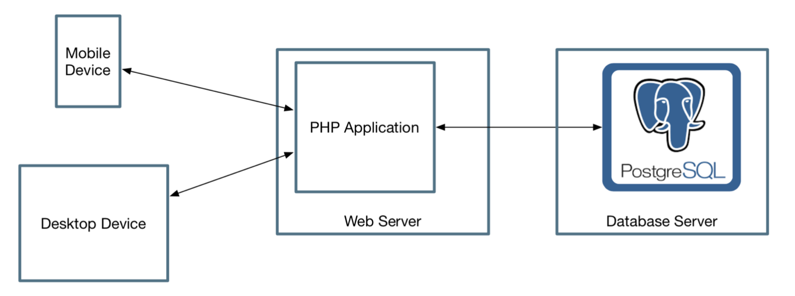
Figure 3: Architecture Diagram for a web system to manage assessment dates
The diagram highlights that the system design has an application written in PHP. It is hosted on a machine that hosts a Web Server. The diagram could be more specific and identify the type of server if appropriate, e.g. Apache, Nginx or IIS. A database is used in the application and it is hosted on a separate server. There is also access from mobile devices and desktop devices. The discussion could go on to talk about these different elements and the software necessary.
The example shows a Mobile Device and a Desktop Device. This has been included as an example where there is some significance about the way that the two types of devices are handled. Perhaps the web server will send different information depending on whether the destination is a mobile or desktop device. If there is no difference, then the diagram could be simplified to show one type of device.
For this example, there is also the question of the interactions between the different parts of the system. In the example the communication is two-way, but in some applications, there may be parts that are only one-way, e.g. saving information that is read by a different program. Again, discuss what these interactions are and identify what information is being transferred.
The above example covers a system that runs on multiple computers. That type of diagram on can be useful for a system that only runs on one computer. Whether on one computer or across multiple computers, highlight the main blocks of the application and how they connect together.
Some projects will focus more on the algorithm and how that works with some existing framework. In that situation, an architecture diagram could still be useful to explain how the code developed on the project relates to the framework being used.
UML class diagram
A class diagram might be useful to describe the main elements that exist in the system. These might be items that hold data or do processing. This may be better suited to Object-Oriented designs, but a class diagram could be a reasonable way to describe the structure of the parts of the code. This is something that can be discussed with supervisors to identify appropriate representation for a project.
Persisting data
Most applications will need to persist data. Typical options might include relational databases and NoSQL data stores. Think about appropriate ways to discuss the design of the data.
An entity-relationship diagram can be useful to explain the structure of the data in relational database. It is one possible format. Look at CS27020 for ways on which to represent entities (i.e. the tables) in a database and the relationships between those entities.
Describing behaviour
A design is not just about the structure - i.e. which items of code exists. A good design should also talk about the behaviour of the more complex elements of the code.
It isn’t necessary to describe the behaviour for all of the code, but it would be good to see discussion of the more complex parts. The aim is to help the reader understand what processing is taking place in the code and how different parts of the system work together.
One way of describing the behaviour is to talk about the algorithm - the sequence of steps to perform a task. This is something that can be discussed with supervisors to obtain advice specific to each project.
Another way to talk about the behaviour in a design is to use some diagrams. One example is the UML Sequence Diagram, which are better suited for Object-Oriented systems. Classic Flow Charts may be suitable for other types of systems.
User interface
Where there is a design for the user interface (UI), it is good to see discussion of the UI design. Screenshots of the final software don’t really show what design was planned. Go back to diagrams that that were prepared when considering possible designs. Discuss how they helped to identify the final design.